

Sensor Data
| Switch mounting: | On the inner side of the track. 45 mm below the surface of the track on a new rail typically |
|---|---|
| Activation: | By the wheel flange passing over the sensor |
| Rail profiles: | 90 RA, 100 RE, 115 RE, 119 RE, 132 RE, 136 RE, 140 RE, 100 RA, 100 ASCE, enquire about others |
| Diameter of wheel | 300 mm to 1000 mm |
| Wheel flange sensed: | 27.5 mm to 36 mm below the upper surface of the rail Wheel flanges lower than 27.5 mm in height may be detected accurately dependent on speeds and how switching distance on sensor has been set after attachment to rai |
| Lateral offset of wheel: | Up to 50 mm |
| Traversing speed: | ≤ 250 km/h (≤ 155 mph) |
| Rail wear: | 18 mm (after 8 mm, the sensor is mounted 9 mm lower, the spacing disk is removed, or when using two-part spacing disks, the upper disk is removed) |
Static Switching Characteristics
| Switching distance: | 43 mm / - 1 mm + 2 mm (Distance of static sensing) Switch tag ST 37 (80 mm x 200 mm x 1 mm thick) |
|---|---|
| Attenuation length at wheel diameter of: | 300 mm ≥ 170 mm* 600 mm ≥ 200 mm 1000 mm ≥ 270 mm Ex. The detection range for System I or System II wheel diameter of 300mm This is the attenuation length when first entering the detection field of System I or System II and then leaving the field of System I or System II |
| Switching hysteresis: | ≤ 2 mm (in direction of travel) (0.0787”) |
| Repetition accuracy of switching point: | ≤ 0.5 mm ≤ 0.1 mm at constant temperature (0.00393”) |
| Switch-on distance: | ≥ 90 mm* The distance between detection at System I and then at System II. First the wheel will be detected at System I and then 90mm later the wheel will be detected at System II. |
| Overlapping coverage of systems | ≥ 70 mm* (2.755”) The detection area of 70mm is the area that both internal systems (System I and System II) are detecting the wheel at the same time. The area of 70mm is the overlapping coverage of both systems. |
Dynamic Switching characteristic V = 250 km/h (155 mph)
| Pulse length: | ≥ 3.5 ms* If the speed is slower the pulse is longer or if the wheel is bigger the pulse is also longer |
|---|---|
| Offset between the systems: | ≥ 1 ms* |
| Overlapping coverage of systems: | ≥ 2.5 ms* 250 km/h (155 mph) with 300 mm wheel the minimum pulse length when both systems are detecting the wheel With an increasing speed, the impulses in traveling direction change ((e.g. with 9 m/s for approximately 60 mm) |
| Reliability of system against: | Eddy current braking |
| No effect of system: | Through magnetic rail brakes being turned on if assembly and setting of DSS are correct |
* New rail; diameter of wheel 300 mm; Wheel flange 27.5 mm; Wheel offset 50 mm; temperature range -30o - +80o.
Control circuit
Connection sketch:
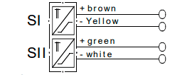
| Operating voltage: | 8.2 V ± 5% ≤ |
|---|---|
| Permanent allowable line resistance: | ≤ 200 Ohm |
| Test voltage between the systems: | 1 kV |
| Test voltage against earth: | 2 kV |
| Lightning arrangement: | Suppressor diode 1.5 kW @ 1 ms |
Wiring
| Cable wires: | 2 each per single rail sensor system |
|---|---|
| Cable wires: | Railway cable, twisted pair in accordance with the DB specification sheet DLK 1.013.20.LY or signal cable in accordance with VDE 0816 |
Housing
| Base plate: | C-Cu-Zn 33 Pb (DIN 1709) |
|---|---|
| Cap: | Plastic, fully cast |
| Connection line: | 4 x 0.75 mm3 polyurethane 5 mm long integrally cast in the housing (PURWIL orange without protective hose can be used in gravel) |
| Overall Dimension: | 7.25”L X 3”H X 3.5”D |
| Weight: | About 5.5 lbs |
| Color: | Grey |
Environment
| Ambient temperature: | -30C to +80C (- 22 oF to + 176oF) |
|---|---|
| Resistant to: | Lightning strike on the rail, through side mounting, effects of weather, UV radiation, greases, oils, bases and salts, acids with some conditions |
| Protective type (DIN 40050): | IP 67 |
| MTBF calculation: | 420,000 h at + 40 oC according to Mil manual 217 d |
| Mechanical vibrations: | 60 g at a frequency range of 25-30 Hz |
| Mechanical load: | < 200 kg (440 lbs.) in the vertical direction |
Assembly
| Fastening: | By 2 Hex Screws M 12 x 35 DIN 609-5.6 by fitting sensor to the rail web. Drilling of rail web necessary for bolt on version (no reduction of rail solidity) With SSK 6 claws for rail foot fastening without need to drill rail. (Assembly of the rail sensor is adjustable). |
|---|---|
| Preferred installation position: | Inner curve of rail |
| Facilitation of mounting: | Approved drilling jig for particular rail profile concerned |
| Maintenance: | See assembly instructions |
| Free zone: | The dimensions must not fall short of those in Figure 1 and 6. Exception: in the movable area of the tongues of the points the dimension 110 (Figure 1) can be reduced to 85 mm, provided that the DSS is not driven over from the adjacent rail. |
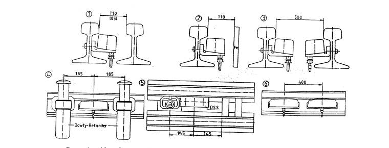
If the installation dimensions are arranged favorably, changes in the height of the wheel cannot destroy the switch
If the rail head is worn away vertically, the switch can simply be moved lower vertically. Threaded drill holes provided for this purpose make it possible to reinstall it in the base plate with no problems. Then another vertical wear of the rail head of 8mm is possible.
In case of lowered mounting of the sensor there is a lateral offset of 16mm towards the left hand side.