
Railway Axle Counting Systems, Railroad Wheel Sensors and Theory
Axle counting systems provide detection of track vacancy through the process of counting wheel flanges as they pass over wheel sensors. A simple axle counting circuit consists of two double wheel sensors, which define the boundaries, or limits of a protected zone of track. Wheel flanges entering this protected zone or “virtual track circuit” are counted in at the entry sensor and counted out at the exit sensor. When one or more axles are present in the axle counting circuit, that zone, or section of track is determined to be occupied in the same manner that the presence of an axle atop a traditional track circuit shunts the track. When the number of axles (wheel flanges) present in the circuit restores to zero,the protected zone is determined to be vacant.
For an axle counting system to function as a virtual track circuit, it is necessary to delimit the axle counting circuit using double wheel sensors. This allows the sensors and associated evaluation equipment to determine direction of movement into, or out of, the circuit, thereby incrementing a counter or decrementing a counter, which in turn controls a suitable relay release module or other ancillary equipment interfaced with a signal system or highway grade crossing signal system.
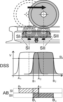
The graphic above represents a wheel flange moving from left to right over a double wheel sensormounted on the gauge side of a rail. In the example above, because the wheel flange is detected atsensor one (S1) first, followed by sensor two (SII), we know the direction of movement is from left to right in the diagram. The associated evaluation equipment, which interfaces and controls the railroad signals, provides the following basic functions:
The evaluation equipment, via a switching amplifier module, excites the electromagnetic field needed to detect the passing wheel flange. This field interacts with the head of the rail and is damped by the passing wheel flange, resulting in an analog impulse.
The evaluation equipment detects the change in voltage drop across the sensor pair, performs interference pulse suppression and then analog-to-digital conversion. This information is sent to a counter module, which can be either a firmware or software device, and, in some cases, also to relay-release module.
The counter is then incremented or decremented to determine track occupancy or vacancy.There are obviously many nuances to the above process, which are too complex to cover in detail here.Suffice to say, the above process incorporates a variety of fail-safe and redundant process to ensure the highest level of safety. As a matter of fact, Pintsch signal systems have never experienced a reported activation failure, despite a quarter century of service on North American freight and transit railroads.
The heart of any axle counting system is the wheel sensor. While the idea of designing a wheel sensor sounds easy to the uninitiated, it is, in fact, a complex problem in the field of applied physics. Consider these factors:
- The wheel sensor must respond consistently to passing wheel flanges under a wide temperature range from sub-zero arctic conditions to triple-digit tropical temperatures.
- The wheel sensor must respond consistently to passing wheel flanges when it is covered in ice and snow, immersed under storm water, or surrounded by industrial byproducts ranging from dirt and aggregates to ferrous taconite pellets.
- The inductive characteristics must remain consistent over years despite exposure to moisture and corrosive contaminants in the nearby environment.
Pintsch wheel sensors are the product of decades of research and development, and manufacturing excellence. This ensures that our axle counting systems perform reliably under all environmental conditions.
A double track crossing approach at a steel-deck bridge. Blue fail-safe double wheel sensor in the foreground.
Vitality (Safety)Vitality, or fail-safe principles are at the heart of the railroad signal and communications field. Our axle counting systems offer multiple layers redundancy and they incorporate carefully designed fail-safe functions. It is for this reason that the fastest rail networks in the world utilize our technology. As with other railroad signaling technologies, our axle counting systems are designed to revert to the most restrictive condition under any fail-safe condition, some examples of which include, but are not necessarily limited to:
- When a sensor is displaced from the rail.
- When a sensor within a double wheel sensor fails.
- When a short or open occurs in the sensor cable.
- When a major change in electrical characteristics of a sensor circuit occurs.
- When an error in the axle counting process is detected in either the counting process or relay functions.
In fact, the level of redundancy, the back-checking processes, and the anti-valent features within our axle counting systems provide a level of redundancy not found in many commonly used railroad signal products of other manufacture.
While all of the details are too extensive to cover in a brief discussion, suffice to say that one may not find the level of safety and redundancy offered by Pintsch on your next commercial airline trip!
ComplexityPintsch axle counting systems can handle any type of track layout, any type of train movement or switching process, and any speed of operation. On-track equipment can enter or exit axle counting circuits from any direction. On-track equipment can be switched through an axle counting circuit in multiple directions and the system will always resolve properly. Any type of railroad signaling application can be managed efficiently through axle counting. Some examples include:
- Island circuits.
- Trap circuits.
- Approach-Island-Approach grade crossing circuits.
- Complex interlocking systems.
- Switch control, protection and yard control functions.
- Speed measurement.
- Red-light overrun and similar PTC functions.
- Industrial process controls
- ….and more.
A few system examples:
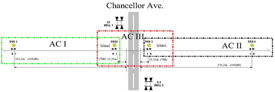
A typical approach-island-approach system
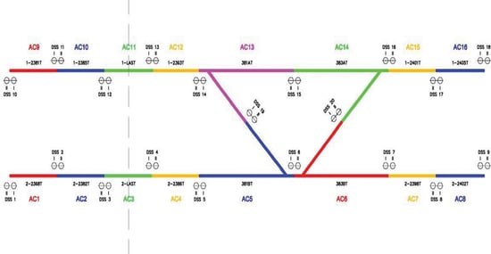
An interlocking system in Minnesota built on axle counting principles.
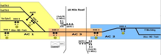
A complex crossing system in Michigan
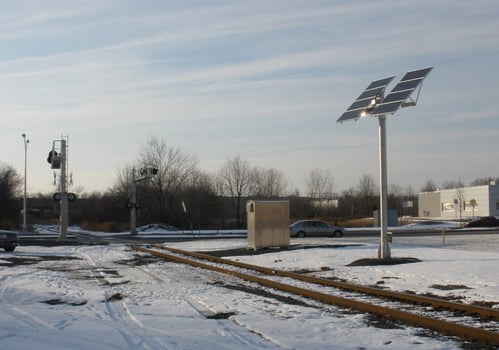
A solar powered crossing powering an axle counting grade crossing system in New Jersey.