The device (R58/37, R58/117 V01 or R58/117/1) contains an electronic calibration unit for each of the sensors SI and SII of the double wheel sensor. The activation of the internal sensors are indicated by LEDs. The power supply of the testing device is provided by a built-in 12-VDC Ni-Cad battery (1.2V x 10).
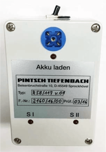
Fig. 1
1 = Connection for signal input of SI and SII
2 = Indicator lamp "Charge battery"
3 = LED indicator lamps SI and SII (switching function)
4 = Battery charging connection
5 = Switch "ON" or "OFF"
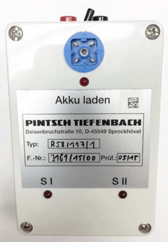
Fig. 2
Fig. 1 Test unit R58/117 V01
Fig. 2 Test unit R58/117/1
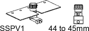
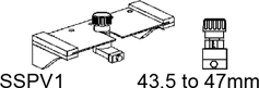
To check the DSS function, you need: – a test unit – and a wheel sensor testing device plate (SSPV)
Version
Test unit
Interface module (AB)
SSPV
For AB with: idle voltage 8V constant current 3.2 mA
R58/117 V01
e.g. for the DSS type: N59-1R-200-45 2N59-1R-200-45 2N59-1R-200-40 2N59-1R-600-40
e.g. for amplifier type: 4AB10/1205/1 4AB10/1105/3 and /32
(small foot)
For AB with: idle voltage 10V constant current 5.2 mA
R58/117/1
e.g. for the DSS type: 2N59-1R-400RE-40
e.g. for amplifier type: 4AB10/1105/35, 4AB10/1105/38, 4AB10/1105/40, 4AB10/1105/43, 4AB10/1105/51
(depending on application) (small foot) (with or without stops)